
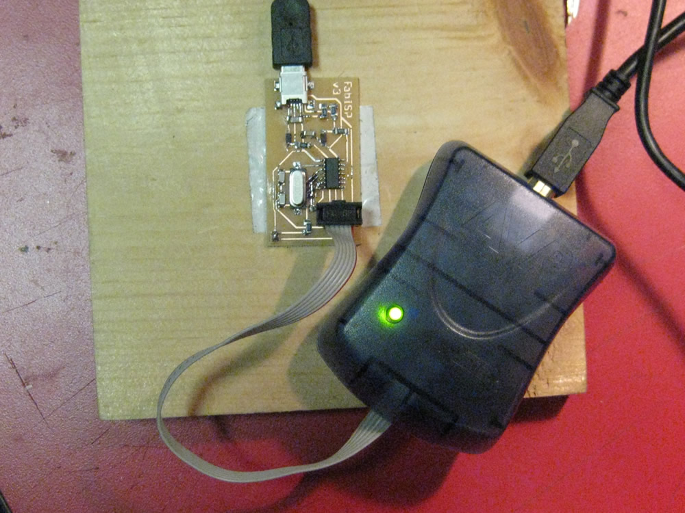
This year the Fab ISP programmer (created by David Mellis) was updated by Neil Gershenfeld. The Electronics Production assignment was to mill the board and stuff it. Most of the students had their boards programmed this week. The board shown is the Fab ISP I made. We will be using these programmers through the semester to program the other boards we create.
To Get Started:
- First – go to the Fab Academy page for Electronics Production and download Neil Gershenfeld’s updated design (shown in this example).
- Then – Read through the MIT Fab ISP page documentation
Mill the Board:
- Mill the board traces (hello.ISP.44.old.traces.png) using the Fab Modules or Cad.py
- Mill out the board (hello.ISP.44.old.interior.png)
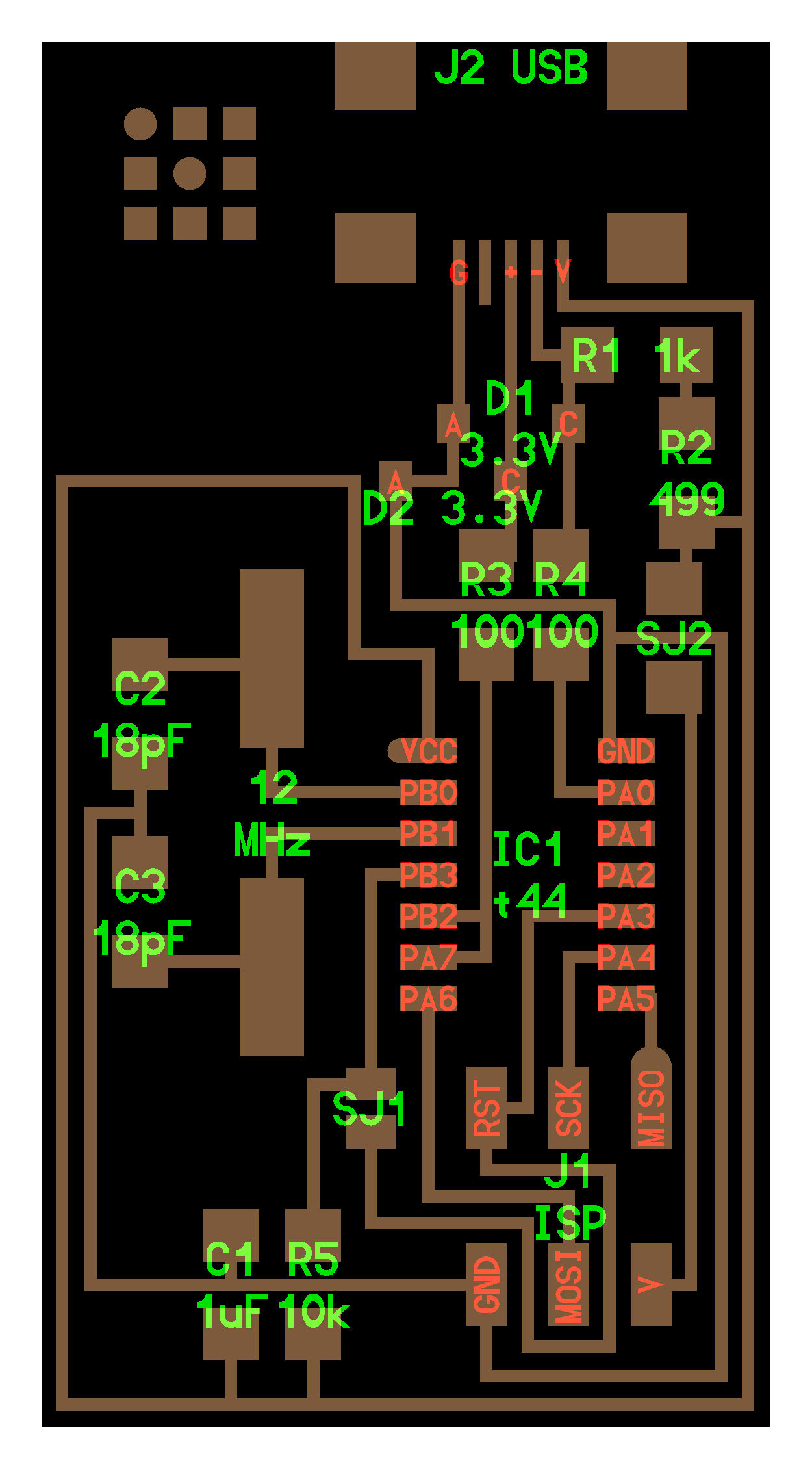
- Labeled board diagram (hello.ISP.44.old.png)


Stuff the Board:
Shawn Wallace has provided a Fab ISP labeled board diagram

“Smoke Test”
- Plug the Fab ISP into your computer via the USB cable.
— If you get an error message from your computer that the board is drawing too much power – and the computer is shutting down the USB port — You have a short somewhere on your board.
Troubleshooting Short Circuits:
- First, do a visual inspection of the board and reflow any solder joints that look cold (not shiny and smooth).
- Then, get out your multimeter and check all the connections to make sure that:
– power and ground are not connected
– there is not a short on the power line
ATAVRISP2 Programmer Light Indicator Messages
If you are using the ATAVRISP2 programmer (or any other programmer that has a indicator light that lets you know if you board is connected / powered correctly). If you connect the programmer to the 6-pin programming header on your Fab ISP board and you get:
- Green Light: means that the header is soldered correctly, the board is getting power and the programmer can sense the microcontroller.
- Yellow Light: means that the board is getting power, but most likely the 6-pin programming header is not soldered correctly (re-flow your solder joints / check for cold joints, check for shorts).
- Red Light: means that the board is not getting power – check for shorts.
Program the Board:
- To program the board, you will need avrdude installed.- For information on where to get and how to use avrdude see: Very Basic Beginner Assembly Tutorial III: How to Use Avrdude
– Also see MIT Fab ISP page documentation - Download the firmware from the Fab Academy Electronics Production page.
- After unzipping the firmware, open a terminal window (mac / linux – for windows instructions see the tutorials listed above).
- Navigate to the downloads folder (or the folder where you saved the firmware).
- The board needs power: make sure that the USB connector for the Fab ISP you are trying to program is plugged in to a computer AND that a separate pogramer is plugged in to the 6-pin programming header. (this could be another working Fab ISP or the ATAVRISP2 mentioned above.)
- In the terminal window type:
make clean
Then type:
make hex
Then type:
make fuse
Then type:
make program
If you get errors – read the errors and follow instructions. If avrdude cannot connect to your board’s microcontroller – you should follow the “Troubleshooting Short Circuits” steps above and ask your instructor for help.
To Verify That Your ISP is working correctly:
Mac OS –> go to the System Profiler >> Hardware >> USB >> Hub:
Step – By – Step:
- Click the “apple” menu in your main toolbar
- Select “about this mac”
- Select “more info”
- Under the “Contents” menu in the left hand navigation- Under the “Contents” menu in the left hand navigation
– Click “Hardware” to expand the hardware menu (if not already expanded)
– Click “USB”
– Under the “USB Device Tree”
– Click “Hub” to expand the hub menu (if not already expanded)
– “FabISP” should be listed in the hub menu - Your Fab ISP device has been successfully programmed and is recognized by your computer.
Linux:
- Still working on this……. details coming soon.
After You Have Programmed the Board:
- Remove the 0 ohm resistor and solder bridge as shown in the picture below.


